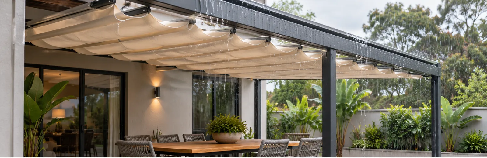
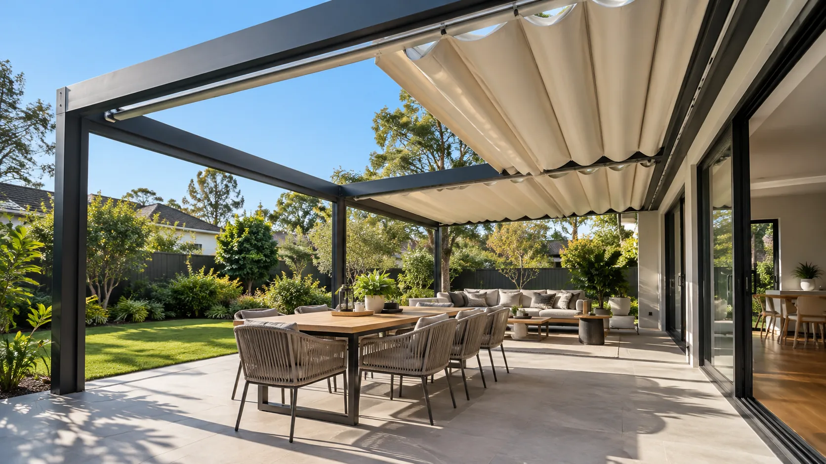
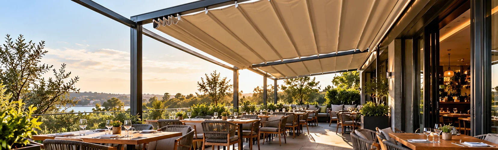








A retractable fabric roof can look almost identical in two finished terrace photographs while relying on completely different supporting structures. One installation transfers part of its load into a building wall. Another stands independently on its own posts and foundations. A third uses a separately supplied frame carrying only the purchased roof assembly.
For importers, distributors, installers, architects and hospitality buyers, that difference matters before requesting a price. It affects structural drawings, building connections, foundations, usable space, installation scope and responsibility for local works.
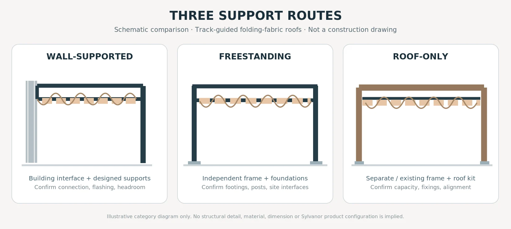
When comparing a wall-mounted vs freestanding retractable pergola, choose the support arrangement before finalising roof dimensions or comparing quotations. Consider wall mounting where the building can accept a properly designed connection. Investigate freestanding support where building attachment is unsuitable or unwanted. Consider roof-only supply where an existing or separately designed frame can be verified as compatible.
This guide covers track-guided folding fabric roofs within a supporting frame. Rotating louvred roofs, roller systems and folding-arm awnings have different mechanisms and interfaces; their installation requirements should not be transferred to a folding fabric roof.
Separate the roof mechanism, support structure and supply scope
Three decisions are often compressed into a description such as “wall-mounted pergola”. Record them separately:
- Roof mechanism: How does the fabric move, in which direction does it travel, and where does it gather when retracted?
- Pergola support structure: Which walls, beams, posts, connections and foundations carry the roof?
- Supply scope: Does the offer include only the moving roof, or also the frame, controls, gutters, installation and local works?
A freestanding structure can sit immediately beside a building. A roof-only pergola kit can mount onto a new steel frame rather than an old pergola. Neither the location nor the purchasing description proves structural suitability.
Ask each supplier to identify the proposed arrangement on a drawing and list the components included. Confirm that the configuration is available for the actual model rather than assuming every product supports all three options.
Compare the three structural configurations
| Decision factor | Wall-mounted / building-supported | Freestanding support frame | Roof-only on a separate frame |
|---|---|---|---|
| Load-bearing arrangement | A designed building connection carries part of the load, with posts or other supports completing the load path | Dedicated beams, posts, connections and foundations carry the roof without relying on the adjoining building | Existing or separately supplied members carry the moving roof through model-specific interfaces |
| Suitable site conditions | A terrace beside a building with an assessable structural attachment location | Open areas or building-adjacent sites where independent support is feasible | A documented existing frame or a new frame designed around the selected roof |
| Wall requirements | Structural substrate, connection capacity and weatherproofing need verification | No structural wall connection; nearby building interfaces still need coordination | Depends on whether the separate frame itself relies on a building |
| Foundation requirements | Front posts and any additional supports require suitable foundations | The full support arrangement needs verified foundations and stability | Existing foundations need assessment, or new foundations need design |
| Installation complexity | Building investigation, fixing access and waterproofing can dominate | Setting out, foundation works, frame assembly and alignment can dominate | Surveying, compatibility checks and frame modifications can dominate |
| Drainage implications | Building flashing and roof drainage form separate interfaces | Discharge must be coordinated with post positions and surrounding surfaces | Existing geometry must accommodate the selected roof’s drainage arrangement |
| Main cost drivers | Building access, connection design, strengthening, posts and making good | Frame quantity, foundations, ground conditions, access and assembly | Structural assessment, adaptation brackets, strengthening and installation access |
| Typical project briefs | Building-adjacent restaurant terraces, hotel dining areas and residential alfresco spaces | Garden hospitality zones, courtyards and detached seating areas | Retrofitting a verified timber pergola or fitting a separately designed steel frame |
This is a procurement comparison, not a structural design or confirmation that any supplier offers every configuration.
There is no reliable price ranking based on support type alone. A wall-mounted arrangement may reduce some frame components but require substantial building work. Roof-only supply may exclude a new frame while adding assessment and adaptation work. Compare the complete installed scope.
Wall-mounted retractable fabric roof pergolas
A common wall-mounted arrangement connects a rear beam or fixing line to the building while front posts support the outward projection. Other layouts are possible, subject to the selected system and structural design.
The first question is what lies behind the finished wall surface. Render, cladding and decorative finishes do not establish a suitable structural fixing substrate. The connection needs to transfer the specified roof reactions into verified building elements.
Check the wall material and connection location
| Existing construction | Information to establish before specifying the connection |
|---|---|
| Concrete | Structural element identity, condition, available fixing locations and constraints around reinforcement or services |
| Masonry | Wall construction, condition, structural role and suitability for the proposed connection |
| Timber-framed wall | Position, size and condition of structural members behind the finish |
| Steel-framed wall | Member positions, sections, connection access and the proposed attachment detail |
| Cladding or insulated facade system | Location of the load-bearing structure and how the attachment passes through the facade |
| Unknown or concealed construction | What investigation is needed before connection design can proceed |
These materials are not automatically suitable or unsuitable. A local designer must assess the actual construction and connection requirements.
Request a marked-up elevation showing the mounting line, doors, windows, eaves, downpipes and services. Identify who will investigate concealed construction and who will repair finishes disturbed during installation.
Coordinate the connection with waterproofing
A structurally adequate fixing does not, by itself, provide a weatherproof building interface. Brackets and fasteners may penetrate finishes or waterproof layers. Flashing, seals and junction details need coordination with the existing wall construction.
Agree who will:
- Design the structural connection and specify its fixings.
- Detail the wall-to-roof junction and penetrations.
- Supply and install flashing or other specified weatherproofing.
- Inspect concealed work before it is covered.
- Complete making good and record the finished installation.
Keep this interface separate from the roof gutter. A gutter does not resolve water entering through an inadequately detailed wall attachment.
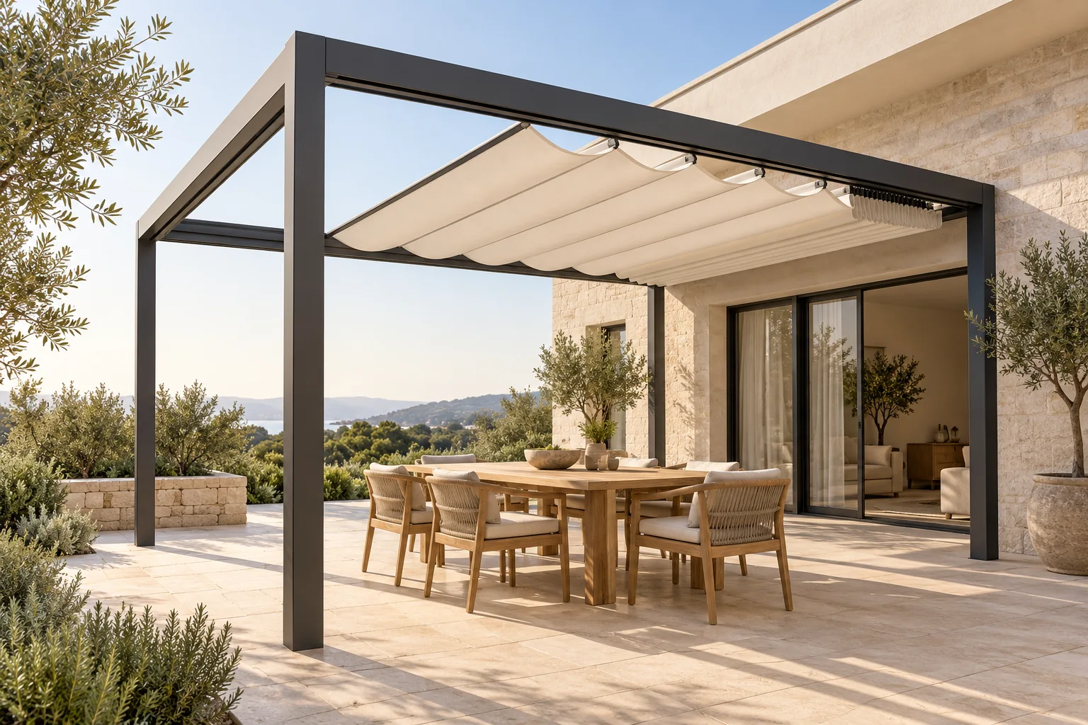
Freestanding retractable fabric pergolas
A freestanding frame carries the roof through its own structural members and foundations. It can be detached from a building or positioned close to one without using it for support, where the design permits.
This arrangement removes the need for a structural wall attachment, but it still requires a complete load path and adequate stability.
Establish where the posts can land
Mark proposed post centres on a measured plan. Check them against:
- Dining circulation, furniture movement and service routes.
- Doors, gates and accessible maintenance positions.
- Existing paving, steps and changes in level.
- Underground services and drainage infrastructure.
- Site boundaries and other constraints requiring local confirmation.
- Space needed for base plates, installation tools and finishing work.
A rectangle showing roof coverage is insufficient for setting out posts. A workable roof footprint may still place a column where staff carry trays or where a door must open.
Verify what supports the posts
Pavers, tiles and decking should not be assumed to act as structural foundations. Establish what lies beneath them and how the post loads will reach suitable support.
Depending on the design, foundation work may involve new footings, cast-in components, base plates fixed to verified concrete, or another engineered arrangement. The local designer must determine the appropriate solution.
For an existing slab, obtain available information about its construction and condition rather than assuming it can accept post anchors. For a deck, elevated terrace or rooftop, assess the supporting structure below the proposed post positions.
Coordinate foundations before concrete work
Where cast-in anchors, embedded plates or other prepared connections are specified, the foundation contractor needs the approved setting-out information before construction.
Confirm post centres, finished levels, orientation, connection geometry and any sleeves or drainage provisions. Identify who checks the installed positions before the frame is dispatched or assembled.
Freestanding does not necessarily mean a standard four-post kit. Additional columns, multiple bays and different beam arrangements depend on the system and project design.
Wall connections and independent foundations: the practical difference
Both arrangements require a verified path for loads to reach the ground. Their procurement risks sit at different interfaces.
With wall mounting, part of that path runs through an existing building. The project team needs to understand the attachment substrate, supporting members and relevant connections beyond the bracket itself.
With independent foundations, the project team needs to establish how posts, bases, foundations and ground conditions work together. Moving the roof away from the wall does not remove these questions.
| Interface | Building-supported arrangement | Independently supported arrangement |
|---|---|---|
| Main investigation | Existing wall and underlying structural members | Ground, existing slab or supporting structure beneath posts |
| Connection design | Brackets and fixings into verified building elements | Post bases, anchors or embedded components connected to designed foundations |
| Prepared works | Opening up, reinforcement or strengthening where specified | Excavation, foundation construction and setting out where specified |
| Weatherproofing | Wall penetrations, flashing and disturbed facade finishes | Base interfaces and any adjacent building junctions |
| Critical coordination | Roof mounting level versus openings and facade details | Post centres and levels versus frame geometry and finished surfaces |
| Evidence before installation | Accepted connection detail and confirmed substrate | Accepted foundation detail and verified completed support positions |
Neither arrangement should be selected solely to avoid professional assessment. Choose the configuration that offers a feasible structural solution and a usable space.
Roof-only supply: checking existing timber and steel structures
A roof-only pergola kit typically supplies the moving roof components for installation onto another structure. The exact package varies: tracks, fabric supports, drive, controls, brackets and gutters may be included or excluded.
Reusing a frame requires more than measuring the opening. A structure originally carrying an open pergola or lightweight covering may not suit the selected retractable fabric roof pergola.
Gather the structural information first
Provide the assessing professional and roof supplier with:
- A plan and elevations showing bays, spans, member positions and heights.
- Beam, post and other relevant member dimensions or section identities.
- Known timber species and grade, or steel section and material information, where documented.
- Joint details, including brackets, bolts, welds and post bases.
- Available foundation drawings and records.
- Original drawings, previous assessments and details of alterations.
- Photographs of the whole frame and accessible connections.
- Evidence of deterioration, movement, repairs or water damage.
- Details of existing coverings and other attached equipment.
Mark missing information as unknown. Do not infer material grades or hidden foundation sizes from photographs.
Existing timber frames
Inspect for decay, splitting, joint movement and deterioration around post bases and connection areas. Previously drilled holes, notches and repairs may affect where new brackets can attach.
A beam can look substantial while its joints or foundations remain unsuitable. The assessment needs to cover the complete load path, including members hidden behind finishes where relevant.
Ask whether the proposed track fixings can be accommodated without inappropriate cutting or drilling. Any strengthening should be coordinated before ordering the roof.
Existing steel frames
Record section identities where available, corrosion, connection condition and any changes from the original drawings. Confirm whether the proposed attachment uses existing holes, new drilling, welding or purpose-designed brackets.
The designer should assess the effect of modifications. Installation documents should also address any required coating repairs and material compatibility where different metals meet.
A steel frame’s apparent rigidity does not establish its capacity or compatibility with the roof’s support geometry.
When a structural engineer needs to be involved
Obtain a structural engineer’s assessment where capacity cannot be established, structural alterations are proposed, deterioration is present, or the supporting arrangement is uncertain.
Engineering review is also necessary where required by the local design or approval process. Confirm those requirements with the relevant local authority or project designer.
For roof-only procurement, the review should resolve:
- Whether the existing members, joints and foundations can carry the selected roof.
- Whether support spacing and alignment suit the actual tracks.
- Whether movement or deflection could interfere with operation.
- What strengthening or connection changes are needed.
- Which drawings and verification records must be completed before installation.
A supplier’s statement that a roof suits timber or steel structures does not approve an individual frame.
Reserve space for the retracted roof
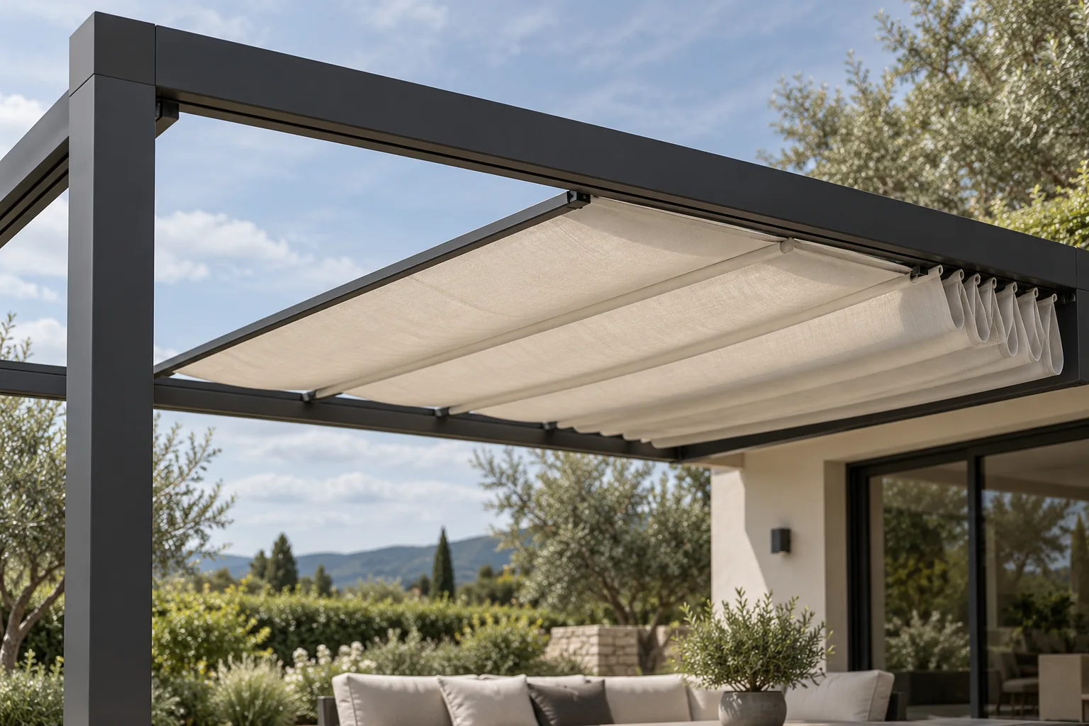
“Retractable” describes movement; it does not mean every component disappears. Folded fabric, support profiles, tracks, drive components and structural beams remain.
Ask for a model-specific drawing showing the roof fully extended, partly open and fully retracted. The drawing should distinguish coverage dimensions from the total installation envelope.
Confirm the fabric stacking zone
Request the actual parked-fabric envelope for the quoted configuration:
- Stack length in the direction of travel.
- Stack width across the roof.
- Depth below or above the relevant reference line.
- Position relative to the rear beam and wall.
- Required clearances around moving components.
- Access space for inspection, adjustment and replacement.
Do not apply a generic stacking percentage or a dimension taken from another model. The space required depends on the selected assembly and configuration.
If admitting sunlight is a project objective, show where the parked fabric remains. A fully retracted roof can still shade part of the area.
Allow for posts, tracks and surrounding obstacles
| Space to reserve | What to check |
|---|---|
| Post and base area | Column footprint, connection access and finished usable circulation |
| Track envelope | Track position, end details, brackets and clear travel path |
| Door and window operation | Full opening movement beneath or beside beams and stacked fabric |
| Accessories | Clearance to heaters, lights, fans, signage and other equipment |
| Maintenance access | Reachable motors, controls, fasteners and replaceable components |
| Nearby structures | Eaves, balconies, vegetation and adjacent roofs throughout operation |
Measure headroom beneath the lowest relevant component, including the parked fabric. Record finished floor levels and any slope across the site.
For roof-only work, check the entire movement envelope against existing beams and braces. An opening can be large enough for coverage while still obstructing the mechanism.
Keep drainage checks specific to the support choice
Drainage affects structural selection where it changes frame geometry, post positions or building interfaces. Detailed gutter sizing and discharge design belong in a separate drainage review.
| Configuration | Essential drainage question before ordering |
|---|---|
| Wall-mounted | How will the building junction be weatherproofed, and where will the roof’s supplied drainage connect to site drainage? |
| Freestanding | Where will water leave the frame, and does that route conflict with post foundations, paths or occupied areas? |
| Roof-only | Can the existing frame accommodate the required roof geometry, gutter position and discharge connection? |
Confirm whether the actual model is intended for rain use and request its operating instructions. Fabric alone does not establish the rain performance of the complete assembly.
If a downpipe is intended to follow or pass through a post, confirm the actual product detail before foundation work. Do not assume every post incorporates drainage.
For gutter capacity, outlets, overflow and discharge planning, refer to Sylvanor’s dedicated drainage article. Keep those calculations and details in the drainage package rather than duplicating them in the structural selection brief.
Assign responsibilities before issuing a purchase order
Supply-only procurement leaves several interfaces with the local project team. An imported package may include an aluminium frame and motorised roof components while excluding foundations, building fixings, electrical connection and approvals.
Use the following matrix to assign named organisations or individuals. The final allocation belongs in the project agreement.
| Workstream | Supplier information or scope to confirm | Local responsibility to assign |
|---|---|---|
| Product configuration | Named model, support options and component list | Acceptance of the proposed arrangement for the project |
| Structural inputs | Available reactions, fixing requirements and model drawings | Assessment of the building, separate frame and foundations |
| Wall connection | Included brackets and attachment requirements | Connection design, substrate verification and installation |
| Foundations | Base geometry and product interface information | Ground assessment, foundation design, construction and setting out |
| Drainage | Supplied gutters, outlets and required roof geometry | Site discharge, building junctions and associated works |
| Mechanical installation | Assembly instructions and stated installation requirements | Site assembly, alignment, fixing and inspection |
| Electrical | Drive details, control components and connection instructions | Electrical design, supply, wiring and connection by the appropriate local electrician |
| Approvals | Available documents for the actual product | Confirmation of requirements with local authorities and project designers |
| Handover | Operating instructions, maintenance information and parts identification | Commissioning records, user instruction and maintenance allocation |
Request available technical evidence for the quoted model. Do not treat a generic brochure or an unrelated test report as proof for the proposed assembly.
Confirm local requirements with the relevant authority or designer before procurement and construction. Product names such as “pergola”, “canopy” or “retractable roof” do not settle the approval pathway.
Compare complete quotations
Require each bidder to mark major items as included, excluded or awaiting confirmation. An unanswered scope question should remain unknown.
| Quotation item | Included / excluded / unknown | Responsible party |
|---|---|---|
| Named roof model and agreed layout | ||
| Fabric, tracks and moving support profiles | ||
| Beams, posts and frame connections | ||
| Brackets and site-specific attachments | ||
| Structural assessment and design | ||
| Foundations and groundworks | ||
| Gutters and site drainage connections | ||
| Motor, controls and electrical works | ||
| Installation, access equipment and commissioning | ||
| Packaging, freight, unloading and storage | ||
| Drawings, instructions and handover documents | ||
| Warranty terms and replacement-parts information |
Compare finish and colour selections as well as component scope. Record any assumptions affecting delivery, assembly or maintenance access.
A lower supply total is not a complete project comparison when another offer includes the support frame or installation. Resolve exclusions before using quotations to select a configuration.
Copy-ready RFQ checklists
Use the common brief below, followed by the checklist for the preferred arrangement. Preliminary enquiries can contain approximate dimensions, provided they are clearly labelled.
State units consistently. If a survey arrives in metres and fabrication information uses millimetres, label the conversion and reference points explicitly.
Common project brief
- Buyer organisation and contact:
- Buyer role: importer / distributor / installer / architect / project procurement:
- Project location and intended use:
- Number of roof systems or zones:
- Preferred roof mechanism: track-guided folding fabric:
- Approximate width, projection and required clear height:
- Measurement reference points and units:
- Preferred opening direction and fabric parking position:
- Site plan, photographs and available drawings:
- Intended weather use and operating questions:
- Motorised operation and control preferences, if applicable:
- Finish and colour preferences:
- Delivery access and installation constraints:
- Required supply scope:
- Target procurement and installation programme:
- Documents requested: layout, component schedule, interfaces, installation instructions, operating limits and available technical evidence:
- Items still awaiting local assessment:
Wall-mounted RFQ additions
- Building construction and known structural substrate:
- Proposed rear attachment line and mounting height:
- Doors, windows, eaves and services near the fixing zone:
- Available building drawings or investigation records:
- Preferred front-post positions and prohibited locations:
- Party assessing the existing building:
- Party designing and installing wall connections:
- Party detailing flashing, penetrations and making good:
- Required parked-fabric clearance:
- Foundation status for remaining supports:
- Requested supplier inclusions and explicit exclusions:
- Outstanding design or approval questions:
Freestanding RFQ additions
- Proposed frame position on the site plan:
- Preferred post centres and circulation restrictions:
- Ground surface and known underlying construction:
- Existing slab, deck or elevated structure information:
- Available foundation or ground investigation records:
- Underground service information:
- Party designing and constructing foundations:
- Required base or embedded-component interface drawings:
- Clearance from nearby buildings and obstacles:
- Proposed drainage exit locations:
- Assembly and lifting access:
- Requested frame inclusions and outstanding local works:
Roof-only RFQ additions
- Existing or separately designed frame material:
- Plan, elevations, spans and support spacing:
- Member sections and documented material information:
- Joint, post-base and foundation details:
- Frame condition and alteration history:
- Original drawings and structural assessment status:
- Proposed track support and fixing locations:
- Measured alignment, levels and opening dimensions:
- Available fabric stacking and maintenance space:
- Proposed roof geometry and drainage interface:
- Party approving compatibility and any strengthening:
- Exact roof-kit contents required, including brackets, drive, controls and instructions:
- Assumptions requiring confirmation before manufacture:
Release the order only when the interfaces are clear
Before committing to manufacture, recognise the difference between an indicative layout and an accepted installation arrangement.
Check that the selected model, support configuration and supply boundaries match across the quotation, drawing and purchase order. Confirm who approves final site measurements, who accepts structural compatibility and how drawing revisions will be controlled.
For wall-mounted systems, resolve the building connection and weatherproofing interface. For freestanding systems, resolve post locations and foundation interfaces. For roof-only supply, resolve the existing frame assessment and track compatibility.
Record any remaining conditions and identify which ones must be closed before manufacture, dispatch or installation. This gives the supplier and local team a shared basis for proceeding.
Prepare a clearer enquiry to Sylvanor
Start with what will support the moving roof, then define which parts you want to source. A marked-up plan, site photographs and the appropriate RFQ checklist provide a useful basis for discussing the configuration.
Send your project requirements to Sylvanor to request a quotation and confirm the available product and supply scope. Include your project location, intended use, quantity, approximate dimensions, preferred support arrangement and programme. For existing structures, attach available frame drawings and identify which structural checks remain outstanding.